BMC Part 4 - Interrupts
In this tutorial, we're going to look at using interrupts to generate the LED flash. Interrupts are an essential ingredient in embedded programming. We're going to investigate the BCM2835/6 interrupt process and implement an interrupt for the ARM Timer peripheral to blink the LED. I appreciate that blinking an LED is probably starting to get boring, but small steps are the way to learn a big system, and learning how to handle interrupts will be enough of a learning curve without having to change what we're doing at the same time. In the next tutorial we'll move away from blinking an LED.
Reference Material
We need some reading material for this tutorial - this is how I put the tutorial together, by reading and studying the manuals available for the processor. Yes there's a lot of text and more than one manual - but that's the only way you learn!
The material that's useful:
- ARM1176JZF-S Technical Reference Manual
- BCM2385 ARM Peripherals
- ARMv6 Architecture Reference Manual This requires agreeing to an NDA to get hold of the PDF version of the document, but it's at least free and easy to get! This document also describes the ARMv7 architecture which the Cortex A7 uses in the BCM2836 (Raspberry-pi 2)
All of those documents, and an ARM instruction set reference are useful for this tutorial.
The Code
The code for the tutorial is hosted on GitHub. The best thing to do to get the code is to clone the repo if you haven't already. Otherwise you can grab the zip of the latest code instead - but you won't be able to get fixes when they're released! ;)
Some of the code that's specific to the tutorial and differs from the last tutorial will be discussed here.
This tutorial only uses the part-4/armc-013 folder.
Interrupts
Let's get straight what an interrupt is. In terms of the ARM processor we're using an interrupt is simply a type of exception. An exception in the processor causes the PC (Program Counter) to be set to a pre-defined value. This pre-defined value will cause code execution to be interrupted and for code execution to run an exception handler put the pre-defined position. At the end of this exception handler control is generally returned to the previously executing code. Exception handlers should be quick and concise as they can occur frequently and obviously take time away from the main code.
Interrupt signals are generally created by hardware. The exception we all know, possibly without realising it is the reset signal. If we strobe the reset line the PC is set to 0 and execution starts from this address. Reset is a bit special though, there's no way to return from the reset exception! All other exceptions can be returned from because the previous PC value has been saved.
Although I've stated above that when resetting a processor, execution starts at address 0, this is not always correct. For example in many processors that support bootloaders the reset value can be different so that the application code starts at address 0 and the bootloader code starts somewhere else. Upon strobing the reset line execution will start at the reset vector, which can be different to 0. The important thing here is simply the term vector. A vector is a value that will be loaded into the processors PC when a given condition occurs.
Each exception type has a vector, and these vectors reside next to each other in memory in what's termed the vector table. See, it's all pretty easy really! The base address of the vector table is 0. Vector tables come in a few varieties, either each vector is simply a value to be loaded into the PC to start execution at a linker-determined position, or else the vector is code that will be executed straight away without any need to do another PC load.
For the ARMv6 architecture the vector table is at memory address 0 and is organised like below, from section A2.6 of the ARM Architecture Reference Manual covering ARMv5 and ARMv6. Please note, that on the ARM documentation website all you'll see is a reference to ARMv6-M or ARMv5. ARMv6-M is for the Cortex-M range of processors which are designed to be more heavily embedded than the application processors (The Cortex-A range), so make sure you get the ARMv5 document which also covers the ARMv6 architecture (which is what the ARM1176JZF-S is).
For the Raspberry-pi 2 which uses the Cortex A7 processor the same table can be found in the ARMv7 reference manual in section B1.8.1 (Table B1-3). It is essentially the same.
| Exception Type | Mode | VE | Normal Address | High Vector Address |
|---|---|---|---|---|
| Reset | Supervisor | 0x00 | 0xFFFF0000 | |
| Undefined Instruction | Undefined | 0x04 | 0xFFFF0004 | |
| Software Interrupt (SWI) | Supervisor | 0x08 | 0xFFFF0008 | |
| Prefetch Abort | Abort | 0x0C | 0xFFFF000C | |
| Data Abort | Abort | 0x10 | 0xFFFF0010 | |
| IRQ (Interrupt) | IRQ | 0 | 0x18 | 0xFFFF0018 |
| IRQ (Interrupt) | IRQ | 1 | Implementation Defined | |
| FIQ (Fast Interrupt) | FIQ | 0 | 0x1C | 0xFFFF001C |
| FIQ (Fast Interrupt) | FIQ | 1 | Implementation Defined |
As you can see, as we've been discussing, the reset vector is at address 0. The next vector is for us to deal with an undefined instruction exception, an unlikely scenario, but something we can at least trap and debug at some point. Following that we have the Software Interrupt, Pre-fetch abort, Data Abort, IRQ (Interrupt) and FIQ (Fast Interrupt) exception vectors. The vectors are sequential except between Data Abort and IRQ where there is an 4-byte gap. The note above the table in the document reads:
NOTE: The normal vector at address 0x00000014 and the high vector at address 0xFFFF0014 are reserved for future expansion.
Vectors are only 4-bytes (one 32-bit instruction) apart. We know therefore the reset vector is simply going to be a branch instruction to the start of our actual code so that the undefined instruction exception can be implemented too. In fact, each of these vectors is simply a branch instruction to a handler somewhere else in memory.
The Normal Address is what we're interested in on the Raspberry-Pi. The High Vector Address is selected in hardware, and that hardware doesn't exist, so the vectors reside at the normal addresses. It's useful, as I've said before to have another place to start executing code if we need a different application installed such as another bootloader or something. We can ignore the High Vector Addresses.
Then we have the Mode column - this is going to be very important. If we look at the vector table, the mode listed for the reset vector is Supervisor.
Processor Modes
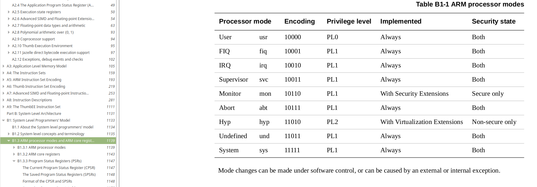
Further back in section A2.2 of the ARM Architecture Reference Manual the documentation covers processors modes. When the processor is reset it is running in Supervisor mode, which is known as a privileged mode. From this operating mode we can write to most of the processors registers and can also change the processors current mode. The only mode that cannot change modes is User - this is designed to execute applications, whereas the privileged modes are meant for operating system tasks.
There is basically a mode per exception. As was mentioned previously we start at the reset vector in Supervisor mode, so far all of our code has operating in that single mode. However, when an exception occurs the processor changes mode to the exception-specific mode. The mode can also be changed in software too if necessary.
The next section of the Architecture Reference Manual describes the registers available. This is again, another important section. Look at Figure A2-1 (Register Organization) and you'll see something interesting...
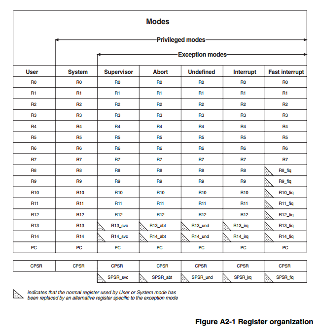
As seen by the small icon and note at the bottom of the table, some of the registers are mode-specific. This can be useful, for example in the Fast Interrupt exception a lot of registers have been replaced by mode-specific registers. This means that we can use these registers without fear of altering the behaviour of code that was operating in User or Supervisor mode before the Fast Interrupt Exception occurred.
Normally, the first thing we would need to do in an interrupt handler would be to save the registers we're going to use and the last thing we'd do in an interrupt handler would be to restore those registers values to what they were before the interrupt handler executed. The code like this at the start of a function or interrupt handler is called the prologue and the code at the end of the function or handler is known as the epilogue.
The shadow register implementation means that many times there's no need to save and restore registers in a Fast Interrupt service routine.
Coding Interrupt Handlers
Providing interrupt handlers can be a bit tricky. It's generally entirely non-portable and you'll have to read the manual for your toolchain in order to understand how to write them. This generally involves informing the compiler that a function you declare should be used to handle a type of interrupt. The toolchain can them fill the vector table with the necessary information. The vector table is usually present in the linker script which defines the memory layout of the target device. because normally these vectors are read-only.
For gcc and ld we can look at the gcc manual on function attributes relating to ARM. https://gcc.gnu.org/onlinedocs/gcc/Function-Attributes.html
It reads:
Use this attribute on the ARC, ARM, AVR, CR16, ... ports to indicate that the specified function is an interrupt handler. The compiler generates function entry and exit sequences suitable for use in an interrupt handler when this attribute is present.
NOTE, for the ARM, you can specify the kind of interrupt to be handled by adding an optional parameter to the interrupt attribute like this:
void f () __attribute__ ((interrupt ("IRQ")));Permissible values for this parameter are: IRQ, FIQ, SWI, ABORT and UNDEF.
The parameter options align well with the vector table we got from the manual. Reset is an ABORT type, and everything else has a parameter available.
Therefore to write a very basic "undefined instruction" handler we can define declare and implement our handler like this:
/**
    @brief The undefined instruction interrupt handler

    If an undefined instruction is encountered, the CPU will start
    executing this function. Just trap here as a debug solution.
*/
void __attribute__((interrupt("UNDEF"))) undefined_instruction_vector(void)
{
    while( 1 )
    {
        /* Do Nothing! */
    }
}
While it looks like this is useless code, it is actually pretty useful. We can set a breakpoint on the while(1) and debug whilst looking out for this breakpoint to trip. Usually then we can do some stack unwinding (manually!) to find where the source of the undefined instruction.
Coding Vector Tables
A strange title that, Coding Vector Tables. With many embedded processors there's no coding or runtime setup of vector tables - instead the vector table is defined in the linker script and the toolchain fills in those locations with the address or jump instruction necessary to execute the relevant handler.
The Raspberry-Pi vector table is extremely small, and it can be like this because some extra work is required in the Interrupt handler compared to more embedded processors such as the Cortex M range. No matter what the Interrupt source is, the same function is called. Inside the Interrupt handler we must work out what the source of the interrupt was before handling that interrupt. Essentially you end up with a large switch structure inside the interrupt handler. You can of course call other functions from the interrupt handler, but again think about the cost of the prologue and epilogue before you do!
When the raspberry-pi starts running our code, as we've discovered earlier in the turotials it loads the code from the SD card to RAM at address 0x00008000 and then starts executing the code. So how can we possibly code the vector table and get the correct jump instructions into the vector table?
Well, everything is in RAM and that's the key - this is read/write memory and in supervisor mode we can write to any location we want. So at runtime when our code is being executed we can overwrite the vector table at runtime. All we need is a vector table to write.
Let's have a look at what needs to be done to implement the vector table. It's easiest if we drop down to assembler to do this. It really could do with being done as the very first thing in our code anyway so it's setup right from the start.
Here is some modified assembler for our _statup: label which is where our linker knows we want to start execution. The linker makes sure this is at the start of our binary:
At fist, I thought this was going to be easy - we just hard-code some values into a table and copy that table to the start of RAM where the vector table resides. Here's some initial code:
_start:
    ldr pc, =_reset_
    ldr pc, =undefined_instruction_vector
    ldr pc, =software_interrupt_vector
    ldr pc, =prefetch_abort_vector
    ldr pc, =_reset_
    ldr pc, =_reset_
    ldr pc, =interrupt_vector
    ldr pc, =fast_interrupt_vector

_reset_:
    // Copy the vector table to the active table at 0x00000000
    ldr     r0, =_start
    ldr     r1, #0x0000
    ldmia   r0!,{r2, r3, r4, r5, r6, r7, r8, r9}
    stmia   r1!,{r2, r3, r4, r5, r6, r7, r8, r9}
There are only a few assembler instructions here, so don't panic! The labels refer to C functions that have been implemented with the correct attributes for each exception type. See the file rpi-interrupts.c to see these C functions.
The Loading of addresses to a register with LDR is documented here
reset and undefined_instruction_vector, etc. are the labels used as the function addresses. So we have a table at the very start of our code. A neat side-effect of having this table right at the start of our code is that the first thing we do is run the reset vector code which jumps to the reset label and starts the execution of our code, thus jumping the vector table we don't want it to try and execute. Excellent!
The ldmia and stmia instructions can load and store 32 bytes of data at a time, so are quick at shifting data about. Each register can load a 4-byte (32-bit) value, so using eight registers lets us move 32-bytes, and there are 8 32-bit vectors in our table, so one load and one store instruction later we've moved the whole of our vector table to 0x00000000.
See the documentation for this on the ARM website
But, before we go too much further, let me show you why this doesn't work!
It's all relative
Compilation of the vector table is successful, but as always just a successful compilation doesn't get you a working application. Earlier in the tutorials I introduced the online disassembler - a great tool, but there's something else in our toolchain's toolbag already, objdump!
That's your friend, and even more friendly is running this from the build directory of the part-4/armc-013/ tutorial folder once you've built the tutorial:
This tells objdump to disassemble the executable and we then redirect objdumps output to the armc-013.diasm file which we can then look at in a text editor. Here's what we get at the start of that file with the vector table implementation I described above:
Disassembly of section .text:

00008000 <_start>:
    8000:   e59ff064    ldr pc, [pc, #100]  ; 806c <_enable_interrupts+0x10>
    8004:   e59ff064    ldr pc, [pc, #100]  ; 8070 <_enable_interrupts+0x14>
    8008:   e59ff064    ldr pc, [pc, #100]  ; 8074 <_enable_interrupts+0x18>
    800c:   e59ff064    ldr pc, [pc, #100]  ; 8078 <_enable_interrupts+0x1c>
    8010:   e59ff054    ldr pc, [pc, #84]   ; 806c <_enable_interrupts+0x10>
    8014:   e59ff050    ldr pc, [pc, #80]   ; 806c <_enable_interrupts+0x10>
    8018:   e59ff05c    ldr pc, [pc, #92]   ; 807c <_enable_interrupts+0x20>
    801c:   e59ff05c    ldr pc, [pc, #92]   ; 8080 <_enable_interrupts+0x24>

00008020 <_reset_>:
    8020:   e3a00902    mov r0, #32768  ; 0x8000
Hmmm, well that doesn't look right, what we'd expect from the first line is an equivalent of ldr pc, #0x8020 which is the reset label is. The toolchain appears to be loading a value far away from where we'd expect. Further down the file we can find the location 0x806C:
0000805c <_enable_interrupts>:
    805c:   e10f0000    mrs r0, CPSR
    8060:   e3c00080    bic r0, r0, #128    ; 0x80
    8064:   e121f000    msr CPSR_c, r0
    8068:   e1a0f00e    mov pc, lr
    806c:   00008020    .word   0x00008020
    8070:   000085e8    .word   0x000085e8
    8074:   000085f4    .word   0x000085f4
    8078:   00008600    .word   0x00008600
    807c:   00008628    .word   0x00008628
    8080:   0000869c    .word   0x0000869c
Some light at the end of the tunnel, the compiler has inserted some constants which are being loaded into the PC so actually, loading the PC with the value at PC + 0x6C is correct for the vector because the value at that location is 0x8020 which is the location of the reset label.
Again, we think this could work after all. But of course, it doesn't. The first part of our code now moves the code from 0x8000 to 0x0000 and the constants have not moved from 0x806C to 0x006C; Neither can we move these constants easily either because the compiler inserts these at the next available space, there's no position we can predict.
The answer is to keep everything relative, but to create some constants of our own. We can keep these constants relative to the LDR PC instruction so that the relative offset still works. We need to create a table of constant addresses after the vector table loads. This way we can copy both tables and the constants will still be in the same position relative to the LDR instructions.
Let's set that up:
_start:
    ldr pc, _reset_h
    ldr pc, _undefined_instruction_vector_h
    ldr pc, _software_interrupt_vector_h
    ldr pc, _prefetch_abort_vector_h
    ldr pc, _data_abort_vector_h
    ldr pc, _unused_handler_h
    ldr pc, _interrupt_vector_h
    ldr pc, _fast_interrupt_vector_h

_reset_h:                           .word   _reset_
_undefined_instruction_vector_h:    .word   undefined_instruction_vector
_software_interrupt_vector_h:       .word   software_interrupt_vector
_prefetch_abort_vector_h:           .word   prefetch_abort_vector
_data_abort_vector_h:               .word   data_abort_vector
_unused_handler_h:                  .word   _reset_
_interrupt_vector_h:                .word   interrupt_vector
_fast_interrupt_vector_h:           .word   fast_interrupt_vector

_reset_:

    mov     r0, #0x8000
    mov     r1, #0x0000
    ldmia   r0!,{r2, r3, r4, r5, r6, r7, r8, r9}
    stmia   r1!,{r2, r3, r4, r5, r6, r7, r8, r9}
    ldmia   r0!,{r2, r3, r4, r5, r6, r7, r8, r9}
    stmia   r1!,{r2, r3, r4, r5, r6, r7, r8, r9}
Note that we've now had to double the amount of data we copy so that we get the constants copied along with the relative PC loads of those constants. This feels like a bit of a cludge but as objdump will show us, this gets the job done and relocates the vector table as required.
The vector table now references the labels directly suffixed to the vector table itself and so the relative position remains constant so long as both are copied as-is.
The output of objdump -S shows us the workable solution:
Disassembly of section .text:

00008000 <_start>:
    8000:   e59ff018    ldr pc, [pc, #24]   ; 8020 <_reset_h>
    8004:   e59ff018    ldr pc, [pc, #24]   ; 8024 <_undefined_instruction_vector_h>
    8008:   e59ff018    ldr pc, [pc, #24]   ; 8028 <_software_interrupt_vector_h>
    800c:   e59ff018    ldr pc, [pc, #24]   ; 802c <_prefetch_abort_vector_h>
    8010:   e59ff018    ldr pc, [pc, #24]   ; 8030 <_data_abort_vector_h>
    8014:   e59ff018    ldr pc, [pc, #24]   ; 8034 <_unused_handler_h>
    8018:   e59ff018    ldr pc, [pc, #24]   ; 8038 <_interrupt_vector_h>
    801c:   e59ff018    ldr pc, [pc, #24]   ; 803c <_fast_interrupt_vector_h>

00008020 <_reset_h>:
    8020:   00008040    .word   0x00008040

00008024 <_undefined_instruction_vector_h>:
    8024:   000085f8    .word   0x000085f8

00008028 <_software_interrupt_vector_h>:
    8028:   00008604    .word   0x00008604

0000802c <_prefetch_abort_vector_h>:
    802c:   00008610    .word   0x00008610

00008030 <_data_abort_vector_h>:
    8030:   00008624    .word   0x00008624

00008034 <_unused_handler_h>:
    8034:   00008040    .word   0x00008040

00008038 <_interrupt_vector_h>:
    8038:   00008638    .word   0x00008638

0000803c <_fast_interrupt_vector_h>:
    803c:   000086ac    .word   0x000086ac

00008040 <_reset_>:
    8040:   e3a00902    mov r0, #32768  ; 0x8000
You can go ahead and see that the armc-013 tutorial is in fact using this solution to provide the exception vector table at run time.
The Interrupt Controller
So now we have the exception vectors tied to our exception handlers (which are implemented in C) but the processor still doesn't know when to interrupt.
Interrupts on a processor are enabled per interrupt source and then globally enabled and disabled. This way we can select which interrupt sources we're interested in and also whether to allow interrupts or not. Sometimes we want to temporarily disable interrupts to guard a non-atomic memory operation if the same memory is used in an interrupt handler for example.
The Raspberry-Pi ARM has an interrupt controller where we can set up the enable and disable the interrupt sources we're interested in. From the BCM2835 ARM peripherals datasheet we can see section 7 describe the interrupt controller present.
The documentation here is a bit lacking - but see the section that says ARM peripherals interrupts table. These are basically the interrupt sources we have control over.
We're blinking an LED and so we just want to capture the ARM Timer interrupt source. In the tutorial code, we will map a C structure to the address of the interrupt controller to give us access to the registers.
This is how we define the struct for the interrupt controller registers and implement an instance at the base address, again this information is from section 7.5 of the document above:
In rpi-interrupts.h:
/** @brief See Section 7.5 of the BCM2835 ARM Peripherals documentation, the base
    address of the controller is actually xxxxB000, but there is a 0x200 offset
    to the first addressable register for the interrupt controller, so offset the
    base to the first register */
#define RPI_INTERRUPT_CONTROLLER_BASE   ( PERIPHERAL_BASE + 0xB200 )

/** @brief The interrupt controller memory mapped register set */
typedef struct {
    volatile uint32_t IRQ_basic_pending;
    volatile uint32_t IRQ_pending_1;
    volatile uint32_t IRQ_pending_2;
    volatile uint32_t FIQ_control;
    volatile uint32_t Enable_IRQs_1;
    volatile uint32_t Enable_IRQs_2;
    volatile uint32_t Enable_Basic_IRQs;
    volatile uint32_t Disable_IRQs_1;
    volatile uint32_t Disable_IRQs_2;
    volatile uint32_t Disable_Basic_IRQs;
    } rpi_irq_controller_t;
and in rpi-interrupts.c:
/** @brief The BCM2835 Interupt controller peripheral at it's base address */
static rpi_irq_controller_t* rpiIRQController =
        (rpi_irq_controller_t*)RPI_INTERRUPT_CONTROLLER_BASE;


/**
    @brief Return the IRQ Controller register set
*/
rpi_irq_controller_t* RPI_GetIrqController( void )
{
    return rpiIRQController;
}
The ARM Timer Peripheral
The ARM timer is in the Basic interrupt set. So to tell the processor we want to enable interrupts from the ARM Timer peripheral we set the relevant bit in the Basic Interrupt enable register:
Also in rpi-interrupts.h:
/** @brief Bits in the Enable_Basic_IRQs register to enable various interrupts.
    See the BCM2835 ARM Peripherals manual, section 7.5 */
#define RPI_BASIC_ARM_TIMER_IRQ         (1 << 0)
#define RPI_BASIC_ARM_MAILBOX_IRQ       (1 << 1)
#define RPI_BASIC_ARM_DOORBELL_0_IRQ    (1 << 2)
#define RPI_BASIC_ARM_DOORBELL_1_IRQ    (1 << 3)
#define RPI_BASIC_GPU_0_HALTED_IRQ      (1 << 4)
#define RPI_BASIC_GPU_1_HALTED_IRQ      (1 << 5)
#define RPI_BASIC_ACCESS_ERROR_1_IRQ    (1 << 6)
#define RPI_BASIC_ACCESS_ERROR_0_IRQ    (1 << 7)
and in our main C code to enable the ARM Timer IRQ:
/* Enable the timer interrupt IRQ */
RPI_GetIrqController()->Enable_Basic_IRQs = RPI_BASIC_ARM_TIMER_IRQ;
The ARM Timer interrupt source is now enabled. However, the processor still needs to have interrupts globally enabled for any interrupt to execute the Interrupt handler, and the ARM Timer peripheral also needs to be enabled and configured to generate the interrupts!
The ARM Timer peripheral is documented in the same BCM2835 ARM peripherals datasheet in section 14.
Again, we map the peripherals register set to a C struct to give us access to the registers:
In rpi-armtimer.h:
/** @brief See the documentation for the ARM side timer (Section 14 of the
    BCM2835 Peripherals PDF) */
#define RPI_ARMTIMER_BASE               ( PERIPHERAL_BASE + 0xB400 )

/** @brief 0 : 16-bit counters - 1 : 23-bit counter */
#define RPI_ARMTIMER_CTRL_23BIT         ( 1 << 1 )

#define RPI_ARMTIMER_CTRL_PRESCALE_1    ( 0 << 2 )
#define RPI_ARMTIMER_CTRL_PRESCALE_16   ( 1 << 2 )
#define RPI_ARMTIMER_CTRL_PRESCALE_256  ( 2 << 2 )

/** @brief 0 : Timer interrupt disabled - 1 : Timer interrupt enabled */
#define RPI_ARMTIMER_CTRL_INT_ENABLE    ( 1 << 5 )
#define RPI_ARMTIMER_CTRL_INT_DISABLE   ( 0 << 5 )

/** @brief 0 : Timer disabled - 1 : Timer enabled */
#define RPI_ARMTIMER_CTRL_ENABLE        ( 1 << 7 )
#define RPI_ARMTIMER_CTRL_DISABLE       ( 0 << 7 )

/** @brief Section 14.2 of the BCM2835 Peripherals documentation details
    the register layout for the ARM side timer */
typedef struct {

    /** The timer load register sets the time for the timer to count down.
        This value is loaded into the timer value register after the load
        register has been written or if the timer-value register has counted
        down to 0. */
    volatile uint32_t Load;

    /** This register holds the current timer value and is counted down when
        the counter is running. It is counted down each timer clock until the
        value 0 is reached. Then the value register is re-loaded from the
        timer load register and the interrupt pending bit is set. The timer
        count down speed is set by the timer pre-divide register. */
    volatile uint32_t Value;

    /** The standard SP804 timer control register consist of 8 bits but in the
        BCM implementation there are more control bits for the extra features.
        Control bits 0-7 are identical to the SP804 bits, albeit some
        functionality of the SP804 is not implemented. All new control bits
        start from bit 8 upwards. */
    volatile uint32_t Control;

    /** The timer IRQ clear register is write only. When writing this register
        the interrupt-pending bit is cleared. When reading this register it
        returns 0x544D5241 which is the ASCII reversed value for "ARMT". */
    volatile uint32_t IRQClear;

    /** The raw IRQ register is a read-only register. It shows the status of
        the interrupt pending bit. 0 : The interrupt pending bits is clear.
        1 : The interrupt pending bit is set.

        The interrupt pending bits is set each time the value register is
        counted down to zero. The interrupt pending bit can not by itself
        generates interrupts. Interrupts can only be generated if the
        interrupt enable bit is set. */
    volatile uint32_t RAWIRQ;

    /** The masked IRQ register is a read-only register. It shows the status
        of the interrupt signal. It is simply a logical AND of the interrupt
        pending bit and the interrupt enable bit. 0 : Interrupt line not
        asserted. 1 :Interrupt line is asserted, (the interrupt pending and
        the interrupt enable bit are set.)  */
    volatile uint32_t MaskedIRQ;

    /** This register is a copy of the timer load register. The difference is
        that a write to this register does not trigger an immediate reload of
        the timer value register. Instead the timer load register value is
        only accessed if the value register has finished counting down to
        zero. */
    volatile uint32_t Reload;

    /** The Pre-divider register is not present in the SP804. The pre-divider
        register is 10 bits wide and can be written or read from. This
        register has been added as the SP804 expects a 1MHz clock which we do
        not have. Instead the pre-divider takes the APB clock and divides it
        down according to:

        timer_clock = apb_clock/(pre_divider+1)

        The reset value of this register is 0x7D so gives a divide by 126. */
    volatile uint32_t PreDivider;

    /** The free running counter is not present in the SP804. The free running
        counter is a 32 bits wide read only register. The register is enabled
        by setting bit 9 of the Timer control register. The free running
        counter is incremented immediately after it is enabled. The timer can
        not be reset but when enabled, will always increment and roll-over.

        The free running counter is also running from the APB clock and has
        its own clock pre-divider controlled by bits 16-23 of the timer
        control register.

        This register will be halted too if bit 8 of the control register is
        set and the ARM is in Debug Halt mode. */
    volatile uint32_t FreeRunningCounter;

    } rpi_arm_timer_t;
and the same in rpi-armtimer.c:
static rpi_arm_timer_t* rpiArmTimer = (rpi_arm_timer_t*)RPI_ARMTIMER_BASE;

rpi_arm_timer_t* RPI_GetArmTimer(void)
{
    return rpiArmTimer;
}
Then, we can setup the ARM Timer peripheral from the main C code with something like:
/* Setup the system timer interrupt */
/* Timer frequency = Clk/256 * 0x400 */
RPI_GetArmTimer()->Load = 0x400;

/* Setup the ARM Timer */
RPI_GetArmTimer()->Control =
        RPI_ARMTIMER_CTRL_23BIT |
        RPI_ARMTIMER_CTRL_ENABLE |
        RPI_ARMTIMER_CTRL_INT_ENABLE |
        RPI_ARMTIMER_CTRL_PRESCALE_256;
As documented the load register is the value loaded into the timer each time the timer elapses. This value is loaded into the Value register either when the register is written, or else when the Value register has counted down to 0. The timer decrements the Value register at a frequency dervied from the system clock.
When the Value register reaches 0 the Value register is re-loaded with the Load value and the interrupt pending bit is set.
It's at this point our interrupt handler should get called. The bits in the Control register that we're setting should be reasonably self-explanatory. Although the documentation says CTRL_23BIT I suspect (as do others) that this is a typo and it's meant to read CTRL_32BIT!
All that's left after configuring the ARM Timer and the Interrupt controller is to globally enable interrupts. This is a function that I wrote in assembler again because the instructions to enable the registers are not available through any C instructions:
In armc-013-start.S:
This code is pretty straight forward. Section A1.1.3 of the ARM ARM describes the Status registers in the processor and describes the Current Program Status Register (CPSR). Some information is covered in this section and of important note is "The CPSR is accessed with special instructions".
Section A2.5 of the ARM ARM describes the format of the CPSR register in more detail and details the exact layout of the CPSR register.
Section A2.5.6 describes the interrupt disable bits, and that gets us the last bit of information we need.
Section A4.1.38 MRS describes the Move Program Status Register to general purpose register instruction which is the special instruction referred to in Section A1.1.3 of the manual.
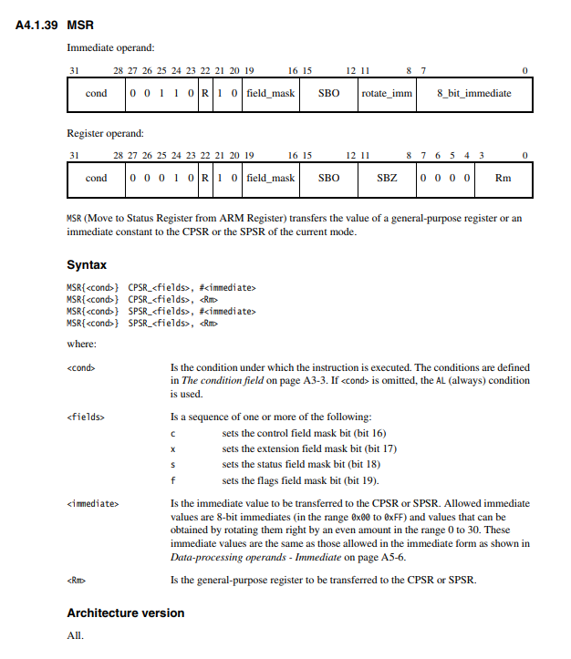
So, we copy the contents of the Current Program Status Register into R0.
Then we clear bit 7 ( Remember (1 << 7) == 0x80 ) in the R0 to enable interrupts. Section A2.5.6 and A2.5 gave us the details for that instruction.
Then we copy r0 back to the Current Program Status Register which is the point at which interrupts become enabled.
Finally we load the Program Counter with the Link Register contents to return from enabling interrupts.
The last thing to do is to write something in the interrupt handler to deal with toggling the LED and to clear the interrupt pending bit. Clearing the interrupt pending bit for the ARM Timer is essential otherwise the processor will not know we have dealt with that interrupt and as soon as it exits from the interrupt handler it will immediately enter it again because the interrupt pending bit of an enabled interrupt source is still set.
The interrupt handler is in rpi-interrupts.c:
void __attribute__((interrupt("IRQ"))) interrupt_vector(void)
{
    static int lit = 0;

    if( RPI_GetArmTimer()->MaskedIRQ ) {
        /* Clear the ARM Timer interrupt - it's the only interrupt we have
           enabled, so we want don't have to work out which interrupt source
           caused us to interrupt */
        RPI_GetArmTimer()->IRQClear = 1;
        /* Flip the LED */
        if( lit )
        {
            RPI_SetGpioHi( LED_GPIO );
            lit = 0;
        }
        else
        {
            RPI_SetGpioLo( LED_GPIO );
            lit = 1;
        }
    }
}
Simples! Our main code now has no code in the main while(1) {} loop because everything is being done in the interrupt handler. In part-4/armc-013/armc-013.c:
void kernel_main( unsigned int r0, unsigned int r1, unsigned int atags )
{
    /* Write 1 to the LED init nibble in the Function Select GPIO
       peripheral register to enable LED pin as an output */
    RPI_SetGpioPinFunction( LED_GPIO, FS_OUTPUT );
    RPI_SetGpioHi( LED_GPIO );

#ifdef RPI4
    gic400_init(0xFF840000UL);
#endif

    RPI_EnableARMTimerInterrupt();

    /* Setup the system timer interrupt
       Timer frequency = Clk/256 * 0x400

       NOTE: If the system decides to alter the clock, the frequency of these
             interrupts will also change. The system timer remains consistent.
    */
#if defined ( RPI4 )
    RPI_GetArmTimer()->Load = 0x4000;
#else
    RPI_GetArmTimer()->Load = 0x400;
#endif

    /* Setup the ARM Timer */
    RPI_GetArmTimer()->Control =
            RPI_ARMTIMER_CTRL_23BIT |
            RPI_ARMTIMER_CTRL_ENABLE |
            RPI_ARMTIMER_CTRL_INT_ENABLE |
            RPI_ARMTIMER_CTRL_PRESCALE_256;

    /* Enable interrupts! */
    _enable_interrupts();

    /* Never exit as there is no OS to exit to! */

    while(1)
    {

    }
}
We now have interrupts up and working and in the exceptions you can do different things with the LED to use them to debug any nasty situations. We'll get onto JTAG debug in a future tutorial, but the next tutorial has to be the mailbox and GPU to get something more interesting happening, and what's more interesting than graphics!?
RPI 4 Interrupts
The Raspberry pi 4 was another shift in architecture. It features a common General Interrupt Controller (GIC) which is a v2 GIC-400 peripheral. This was added to considerably improve the performance of virtualisation. Running Containers on a RPI4 is much more efficient compared to earlier models. Thankfully, the RPI foundation have said this will be the last revision of the same RPI format. It's a nightmare trying to support all of these model differences in a basic tutorial!
The same interrupt controller as the rest of the Broadcom BCM SoCs is still in place and is configured in the same way, except the interrupt line from that controller is fed into the GIC.
At reset this means the interrupt signal will not be routed to the CPU running code in order to be able to respond to the interrupt. We will have to add RPI4-specific code which allows us to configure the GIC peripheral to pass the interrupt signal on to one of the CPU cores. As we're not doing any multi-core work at the moment we can configure the GIC to route all interrupt signals to CPU0 which has our interrupt service routines.
To find where the peripheral is located in memory - we turn to the linux source code:
Knowing that the RPI4 uses the BCM2711 (linked in the kernel source code as BCM2838 ) processor, in keeping with the RPI series helps:
An excerpt from the device tree for the BCM2838 shows the GIC, along with the other interrupt controller:
soc {
  ranges = <0x7e000000  0x0 0xfe000000  0x01800000>,
           <0x7c000000  0x0 0xfc000000  0x02000000>,
           <0x40000000  0x0 0xff800000  0x00800000>;
  /* Emulate a contiguous 30-bit address range for DMA */
  dma-ranges = <0xc0000000  0x0 0x00000000  0x3c000000>;

  /delete-node/ interrupt-controller@7e00f300;
  /delete-node/ v3d@7ec00000;

  local_intc: local_intc@40000000 {
      compatible = "brcm,bcm2836-l1-intc";
      reg = <0x40000000 0x100>;
  };

  gicv2: gic400@40041000 {
      interrupt-controller;
      #interrupt-cells = <3>;
      compatible = "arm,gic-400";
      reg =    <0x40041000 0x1000>,
            <0x40042000 0x2000>,
            <0x40044000 0x2000>,
            <0x40046000 0x2000>;
      interrupts = <GIC_PPI 9 (GIC_CPU_MASK_SIMPLE(4) |
                               IRQ_TYPE_LEVEL_HIGH)>;
  };
The physical address is 0x40041000 - but we can see from the device tree configuration just above that the physical address 0x40000000 is mapped to 0xFF800000 so the GIC400 is available to us at 0xFF841000 - it has four sets of registers define by the reg tag.
In order for CPU0 to receive any interrupt signals, we're going to have to go ahead and configure this peripheral.
In keeping with this tutorial series, let's not get bogged down with trying to over-complicate a driver. All we want to do is configure this peripheral from it's reset state to send all interrupts to CPU0.
Documentation
There is GIC-400 documentation available from ARM.
There is also the ARM GIC Architecture documentation to consider too.
There's a lot of information around secure and non-secure access to the GIC. For now, we don't need to delve too deep. Our task is simple - get interrupts routed to CPU0.
Register Map
The GIC-400 register map is available under the Programmer's Model section of the CoreLink-400 Generic Interrupt Controller documentation.
The Register Map is divided up into function blocks. The functional blocks are defined in section 3.2 as:
- GICD_ Distributor
- GICC_ CPU Interfaces
- GICH_ Virtual Interface control blocks
- GICV_ Virtual CPU Interfaces
We're not interested in the Virtual blocks, but we are of course interested in the other blocks.
The functional block offsets are shown in the table and align with the device tree reg tags above.
| Offset | Block |
|---|---|
0x0000 - 0x0FFF | Reserved |
0x1000 - 0x1FFF | Distributor (GICD_) |
0x2000 - 0x2FFF | CPU Interfaces (GICC_) |
0x4000 - 0x4FFF | Virtual interface control for the process that is performing the access |
0x5000 - 0x5FFF | Virtual interface control for the processor selected by address bits 11:9 |
Later on in the same section is breakdown of all registers in those blocks. It's this information that can be put into code. Then, in order to do a simple enablement of the peripheral, we will configure all available interrupts to be enabled and routed to CPU0.
We have a function that initialises this peripheral in the new gic-400.c file. This file is not rpi-specific because gic-400 interrupt controllers are used by a lot of different SoCs.
This function is conditionally called immediately before configuring the ARM Timer peripheral and the global enabling of interrupts.
We should obviously make this code better, but for now we just know that we need to initialise this controller to get any interrupts working.
When you're ready head over to Part 5